
3.1A • PD Control Example 

 PID Controller
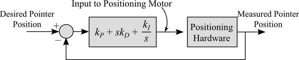
 A linear positioning system is commonly used in manufacturing equipment such as a CNC mill  . These system often use a drive motor and linear screw to move the cutter across the material. The position of the cutter is often controlled using a PID controller. The controller measures the position of the cutter, compares it to the desired cutter position and adjust the input to the drive motor accordingly. A simplified block diagram of such a system is shown in Fig 3.1.2.
A simulation of a CNC system is shown below. As you move the slider on the bottom of the system (the desired position), the controller attempts to moves the cutter (measured position) to match the position of the slider. Experiment with the slider and PID gains. Notice the response of the cutter as it tracks the slider. Also notice how different PID gain values affect the system response.
Notice that increasing kP also decreases the steady-state error of the system. This is typical. As you increase the system gain you decrease the error. In general, however, simply increasing kP is not enough to completely eliminate steady-state error. You must add in integral control.
kD tends to affect the damping of the system. Set kP = 5 and kD=0. Note how long it take for the system to come to rest (Tsettling ≈ 2 seconds).
Now set kD = 0.5. Notice how the system damping changes but the settling time remains the same. However, as you continue to increase kD the systems damping increases eventually lengthening the settling time.
One problem with kD is that it tends to amplify system noise. This should make sense. Noise tends to occur at high frequencies. The derivative of a fast changing (high frequency) value is a large number. In this system you can see the detrimental affects of kD once we add in kI
kI can be used to reduce tracking error and for a step input it can it can complete eliminate the steady-state error. Set kP = 5 and observe the steady-state error (the difference between the pointer location and the slider). Then set kI=5. Notice the steady state error.
The disadvantage of using kI is that small values tend to slows down the response and large values can destabilize the system. Try increasing kI and observe how the response changes
Try the values:
Notice how changing kP in PID controller has a slightly different affect then changing kP in a strictly proportional controller. The addition of kI increases the overall order of the underlying differential equation and so the system response to a given parameter.